- 您现在的位置:买卖IC网 > Sheet目录861 > GCM188R71E154KA37D (Murata Electronics North America)CAP CER 0.15UF 25V 10% X7R 0603
�� �
�
�!� Note� ?� Please� read� rating� and� !� CAUTION� (for� storage,� operating,� rating,� soldering,� mounting� and� handling)� in� this� catalog� to� prevent� smoking� and/or� burning,� etc.�
�?� This� catalog� has� only� typical� speci?cations.� Therefore,� please� approve� our� product� speci?cations� or� transact� the� approval� sheet� for� product� speci?cations� before� ordering.�
�C03E.pdf�
�May.17,2013�
�!� Caution�
�Continued� from� the� preceding� page.�
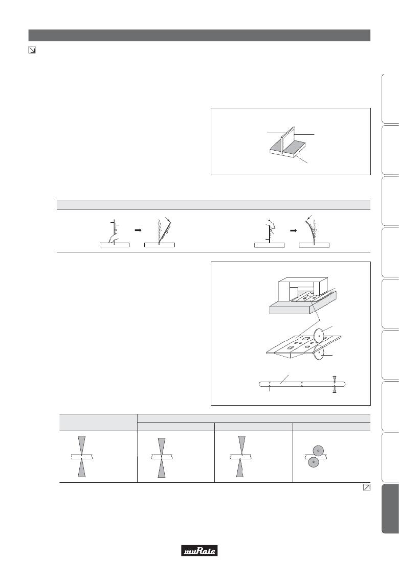
�2.� Check� the� cropping� method� for� the� printed� circuit� board�
�in� advance.�
�2-1.� Printed� circuit� board� cropping� shall� be� carried� out� by�
�using� a� jig� or� an� apparatus� to� prevent� the� mechanical�
�stress� that� can� occur� to� the� board.�
�(1)� Example� of� a� suitable� jig�
�Recommended� example:� the� board� should� be�
�pushed� as� close� to� the� cropping� jig� as� possible�
�[Outline� of� Jig]�
�and� from� the� back� side� of� the� board� in� order� to�
�minimize� the� compressive� stress� applied� to� the�
�capacitor.�
�Not� recommended� example:� when� the� board� is�
�pushed� at� a� point� far� from� the� cropping� jig� and�
�from� the� front� side� of� board� as� below,� the�
�capacitor� may� form� a� crack� caused� by� the� tensile�
�stress� applied.�
�Recommended�
�Printed� Circuit� Board�
�V-groove�
�Board� Cropping� Jig�
�Not� recommended�
�Printed� Circuit� Board�
�Direction� of� Load�
�Components�
�Load� Point�
�Direction� of� Load�
�Load� Point�
�(2)� Example� of� a� suitable� machine�
�An� outline� of� a� printed� circuit� board� cropping�
�machine� is� shown� as� follows.� Along� the� lines� with�
�the� V-grooves� on� the� printed� circuit� board,� the� top�
�and� bottom� blades� are� aligned� to� one� another�
�when� cropping� the� board.�
�The� misalignment� of� the� position� between� top� and�
�Printed� Circuit� Board�
�[Outline� of� Machine]�
�Components�
�Top� Blade�
�bottom� blades� may� cause� the� capacitor� to� crack.�
�[Principle� of� Operation]�
�Printed� Circuit� Board�
�Top� Blade�
�Bottom� Blade�
�V-groove�
�[Cross-section� Diagram]�
�Printed� Circuit� Board�
�V-groove�
�Recommended�
�Top� Blade�
�Bottom� Blade�
�Top-bottom� Misalignment�
�Top� Blade�
�Bottom� Blade�
�Not� Recommended�
�Left-right� Misalignment�
�Top� Blade�
�Bottom� Blade�
�Front-rear� Misalignment�
�Top� Blade�
�Bottom� Blade�
�Continued� on� the� following� page.�
�55�
�发布紧急采购,3分钟左右您将得到回复。
相关PDF资料
GCM31A7U2J471JX01D
CAP CER 470PF 630V 5% U2J 1206
GCM31C5C1H104JA16L
CAP CER 0.1UF 50V 5% NP0 1206
GHF459601ZA6N
CAP ARRAY 6CH 600PF 50V 1404
GL2L5LS050D-T1-C
DELAY LINE 0.5NS +-50PS 16SOIC
GL6R0KA7B200
INDUCTOR BROADBAND 6UH
GP447
CAP CER 47PF 1KV 10% RADIAL
GRF4.0419.013.C
GRF4 APPLIANCE INLET FILTER 15A
GRM022R60J332KE19D
CAP CER 3300PF 6.3V X5R 01005
相关代理商/技术参数
GCM188R71E154KA37J
功能描述:多层陶瓷电容器MLCC - SMD/SMT 0.15uF 25Volts X7R 0.1
RoHS:否 制造商:American Technical Ceramics (ATC) 电容:10 pF 容差:1 % 电压额定值:250 V 温度系数/代码:C0G (NP0) 外壳代码 - in:0505 外壳代码 - mm:1414 工作温度范围:- 55 C to + 125 C 产品:Low ESR MLCCs 封装:Reel
GCM188R71E222KA37D
功能描述:多层陶瓷电容器MLCC - SMD/SMT 0.0022uF 25Volts X7R 10%
RoHS:否 制造商:American Technical Ceramics (ATC) 电容:10 pF 容差:1 % 电压额定值:250 V 温度系数/代码:C0G (NP0) 外壳代码 - in:0505 外壳代码 - mm:1414 工作温度范围:- 55 C to + 125 C 产品:Low ESR MLCCs 封装:Reel
GCM188R71E223KA02D
功能描述:多层陶瓷电容器MLCC - SMD/SMT 0603 0.022uF 25volts X7R 10%
RoHS:否 制造商:American Technical Ceramics (ATC) 电容:10 pF 容差:1 % 电压额定值:250 V 温度系数/代码:C0G (NP0) 外壳代码 - in:0505 外壳代码 - mm:1414 工作温度范围:- 55 C to + 125 C 产品:Low ESR MLCCs 封装:Reel
GCM188R71E223KA02J
制造商:Murata Manufacturing Co Ltd 功能描述:
GCM188R71E223KA37D
功能描述:多层陶瓷电容器MLCC - SMD/SMT 0.022uF 25Volts X7R 0.1
RoHS:否 制造商:American Technical Ceramics (ATC) 电容:10 pF 容差:1 % 电压额定值:250 V 温度系数/代码:C0G (NP0) 外壳代码 - in:0505 外壳代码 - mm:1414 工作温度范围:- 55 C to + 125 C 产品:Low ESR MLCCs 封装:Reel
GCM188R71E223KA37J
功能描述:多层陶瓷电容器MLCC - SMD/SMT 0.022uF 25Volts X7R 0.1
RoHS:否 制造商:American Technical Ceramics (ATC) 电容:10 pF 容差:1 % 电压额定值:250 V 温度系数/代码:C0G (NP0) 外壳代码 - in:0505 外壳代码 - mm:1414 工作温度范围:- 55 C to + 125 C 产品:Low ESR MLCCs 封装:Reel
GCM188R71E224K
制造商:MURATA 制造商全称:Murata Manufacturing Co., Ltd. 功能描述:Chip Monolithic Ceramic Capacitor 0603 X7R 0.22μF 25V
GCM188R71E224KA55
制造商:MURATA 制造商全称:Murata Manufacturing Co., Ltd. 功能描述:Chip Monolithic Ceramic Capacitors for Automotive